Electricity Notes for Class 10 Science
Important terms & concepts
Electricity : A fundamental form of energy observable in positive and negative forms that occurs naturally or is produced (as in generator ) and that is expressed in terms of the movement and interaction of electrons.
Current electricity: The branch of physics which deals with the study of charge in motion is called current electricity.
• Flow of charge in a closed circuit
• Direction of flow of positive charge is the direction of conventional current
• Direction of current is opposite to the direction of flow of electron in a circuit.
Fundamental Property of Matter: Ordinary matter is made up of atoms which have positively charged nuclei with negatively charged electrons orbiting them. So the charge can be considered as a fundamental property of matter.
During any process, the net charge of an isolated system remains conserved (constant) i.e. charge can neither be created nor be destroyed but can only be transferred. This is law of conservation of electric charge.
Electricity: The flow of charge in a closed path carrying energy from the power supply to the different electrical components in the circuit is called electricity.]

Properties of Charge:
• like charges repel and unlike charges attract each other.
• Unit of charge is coulomb (C). One coulomb charge contains nearly 6 ×10¹⁸ electrons.
• net charge of an isolated system remains conserved
• Protons have a positive charge of 1.6 × 10⁻¹⁹ C while electrons carry a negative charge equal to-1.6 × 10⁻¹⁹
C. These are fundamental charges.
• Charges are quantized as an integral multiple of the charge of electron or proton.
Thus, the total charge Q on an integral body is given by

Note : When the charge are at rest then it is called Static electricity.
Electric Current: The amount of charge ‘Q’ flowing through a particular area of cross-section in unit time ‘t’ is called electric current. This leads to the basic formula for current which is

The electric current is scalar quantity.
Flow of electrons in a conductor when cell or battery is applied across its end SI unit ampere (A)
1A=Cs-1
Unit of current: Ampere is the flow of electric charge through a surface at the rate of one coulomb per second that is if 1 coulomb of electric charge flows through a cross-section of wire for 1 second then it would be equal to 1 ampere
In SI system, I A = I C s-1
Electrochemical device: It is a device which convert chemical energy into electrical energy.
Direction of Electric Current:
• In a metal, flow of electron (carrying negative charge) constitutes the current.
• Direction of flow of electron gives the direction of electronic current. By convention, the direction of flow of positive charge is taken as the direction of current.
• This is called conventional current.
• Thus, the direction of current is opposite to the direction of flow of electrons in the circuit
Electric Field: The region or space surrounding the charge where another charge experiences a force of attraction or repulsion depending upon the nature of charge is called electric field or electrostatic field around that charge.
Open circuit : Key is not plugged in and no electric current flows through the electric circuit.
Closed circuit circuit : Key is plugged in and electric current flows through the electric circuit
Electric Potential: The potential difference between two points is one volt when one joule of work is done to carry a charge of one coulomb between the two points in the electric field
• Electric potential (V) at any point in the electric field is given by

• SI unit of electric potential is volt (V) named in honour of the Italian physicist, Alessandro Volta (1745-1827).
• 1 V = 1 JC-1
• Electric potential is a scalar quantity.
Resistance: It is the property of a conductor which opposes or restricts the flow of current through it. It is measured in Ohm’s. The symbol for Ohm’s is Ω. The SI unit of resistance is named in the honour of George Simon Ohm (1787-1854). According to Ohm’s law,
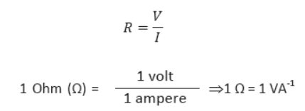
Therefore, 1 Ω is defined as the
“resistance of a conductor which allows 1 A of current through it when 1 V potential difference is applied across its ends.”
Large resistances are conveniently expressed in (1 kΩ = 103 Ω), (1 MΩ = 106 Ω) and small resistances in (1 Ω = 10-3 Ω), (1 μ Ω = 10-6 Ω).
Electric Potential Difference: It measures the work done per unit charge. It is defined as the difference in electric potential between two points in an electric field, equal to the work done per unit quantity of charge in moving it from one point to another in an electrostatic field.

Note: Negative charge always moves from lower potential to higher potential but reverse is true for current.
If both the ends across the conductor are at the same potential, no current flows through it.
One volt: The potential difference between two points in an electrostatic field is said to be 1 volt if one joule work is done in moving 1 coulomb of electric charge from one point to another in the same electrostatic field.
Cell or Battery: Electric cell or battery is the device for generating or storing electrical energy by means of electrochemical reaction.
• Within a cell a chemical reaction occurs that transfers an electron from one terminal (leaving it positively charged) to another terminal (making it negatively charged).
• The chemical energy stored in the cell is responsible for maintaining the current in the external circuit by creating a difference of electric pressure called potential difference.
Conductor
• A substance through which an electric charge can flow easily is called conductor.
• It has high electrical conductivity and low electrical resistance. It has large number of free electrons which are loosely bound with the nucleus.
• Silver, copper and aluminium are the good conductors of electricity.
Insulators
• Those materials which cannot conduct electricity as they have high electrical resistance are called insulators.
• Electrical conductivity is either very very small or negligible.
• The electrons are tightly bounded with the nucleus.
• Glass, rubber, wood, ebonite, bakelite, etc. are some examples of insulators.
Galvanometer: It must be connected in series to detect the current in the circuit.
Voltmeter: It measures potential difference between two point of the circuit and is connected in parallel. It should have a high resistance.
Ammeter: It is used to measure the current in a circuit and is always connected in series. It should have a low resistance.
Electric Circuit: An arrangement for maintaining the continuous flow of electric current by the electrical energy source through the various electrical components connected to each other by conducting wires is called electric circuit. Thus, a complete circuit is the one which is a closed loop.
Circuit Diagram: A circuit diagram is the pictorial representation of a circuit in which different electrical components of the circuit are presented by their symbols.
The symbol for most commonly used electrical components in circuit diagrams are given in the following
table.

Ohm’s Law: It deals with the relationship between voltage and current in an ideal conductor. This relationship states that “the potential difference (V) across the ends of a given metallic conductor in an electric circuit is directly proportional to the current (I) flowing through it, provided its temperature remains the same”. This is called Ohm’s law.
Mathematically, or

The constant of proportionality is called resistance ‘R’ of the given conductor at a given temperature. Ohm’s law can be used to solve simple circuits.
Rheostat: It is a device which is used in the circuit as a current controller, and potential divider by changing its resistance.
Factors affecting the resistance of a conductor: From the above activity, it is observed that the resistance of a conductor depends on

Where, p(rho) is a constant of proportionality and is known as specific resistance or resistivity of the material of the conductor. It depends upon the nature of material. It increases with increase in temperature.
Specific Resistance or Resistivity: Mathematically resistivity of the conducting material is given by
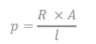
If = 1, A = 1 m2, then = R
Hence, the resistivity of the material is defined as the resistance offered by a metallic wire having a unit length and a unit area of cross-section. Since unit length and unit area of cross-section forms a cube, the specific resistance or resistivity can also be defined as the resistance offered by a cube of a material of side 1 m when current flows perpendicularly through the opposite faces.
In CGS system, its unit is oh-centimeter (Ω cm). In SI system, its unit is oh-meter (Ω-m)
Also, 1 Ω m = 102 Ω cm
• Resistivity of the metallic conductor does not depend on the length or thickness of the wire.
• Metals have low resistivity. So, they are the best conductor of electric current.
• The resistivity of insulators exceeds those of the metal by a factor of the order of 1022.
Alloy: An alloy is a homogeneous mixture of two or more metals or a metal and a non-metal in a fixed proportion.
Example: Nichrome is an alloy of nickel, chromium, manganese and iron metal and bronze is an alloy of Cu and Sn.
Properties of an alloy:
• Resistivity of an alloy is generally higher than that of its constituent metals. So, it has a high resistance.
• Alloys do not oxidize (burn) readily even at high temperature.
• Change in resistivity of alloy due to change in temperature is much smaller as compared to its constituent metals.
Uses of alloys:
• Due to reason (i) and (ii) alloys are commonly used in electrical heating devices such as room heater, water heater, electric iron, toaster, cooking range, etc.
• On account of negligible effect of temperature, alloys are used to make wire of standard resistance, resistance box, rheostat etc.
Resistors in series combination: When an end of one resistor is connected to the beginning of the next and so forth the resistors are said to be connected in series. Figure shows
the three resistors connected in series.
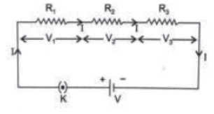
Characteristics of series circuit:
• Total potential difference across the series combination is equal to the sum of the potential difference across the individual resistors i.e., V =V1 + V2 + V3
• In series combination of resistors, same current passes through each resistor.
• Potential difference across each resistor is directly proportional to the resistance of that resistor i.e.
• Equivalent resistance of series combination is equal to the sum of their individual resistance R1, R2 and R3 i.e., R3 = R1 + R2 + R3
• The equivalent resistance is greater than any individual resistance.
Uses of series circuit: It is used when
• Large resistance in the circuit is required
• Current in the circuit is to be reduced
• Less potential deference across a particular resistance is needed.
Resistors in parallel combination: When two or more resistors are connected between two common points whose one end will be at higher potential and other at lower potential in a circuit the resistors are said to be in parallel. Figure shows the parallel combination of three resistors.

Characteristics of parallel circuit:
• Voltage across each resistor is same and is equal to the voltage applied across the combination.
• Current which passes through individual branch of the circuit is inversely proportional to the resistance of that branch i.e.

• Total current I which flows in the circuit is equal to the sum of the currents passing through the individual resistor of the combination, i.e. l= l1+l2+l3
• The reciprocal the equivalent resistance is the algebraic sum of the inverse of individual resistances, i.e.
1/RP = 1/R1 + 1/R2 + 1/R3
• Equivalent resistance of the parallel combination is less than the least resistance of any resistor in the circuit.
Uses of parallel circuit: It is used when
• Resistance in the circuit is to be decreased.
• Current in the circuit is to be increased.
Therefore all the electrical appliances for a household purpose are connected in parallel combination.
Identification of series and parallel combination:
• If there is no branch at the common point then it is a series circuit.
• If there are branches between two common points, then it is a parallel circuit.
Practical applications of series circuit: Series circuits are used for dependent operations such as
• Decorative light string on festivals.
• Thermostats in heating devices to control the temperature.
• Light switches, fuse with lie wire in house hold wiring.
• Batteries to get higher voltage.
• Ammeter to measure the current.
Disadvantages of series circuit:
• More the components circuit has, the greater will be its resistance. Example: On adding a light bulb in decorative string, the bulbs do not shine as brightly as before.
• If the circuit is broken, the entire circuit stops working because circuit becomes an open circuit.
• The electrical appliances need current of widely different values to operate properly, but in series, same amount of current flows through each of them.
Practical applications of parallel circuit:
• Parallel circuits are used for independent operations of all the electrical devices such as light bulbs and other electrical devices in office, homes etc. connected with the main supply.
• Voltmeter measures the potential difference across the load.
• Batteries give more current.
Advantages of parallel circuit:
• If one electrical component is switched off, other works properly.
• Each appliance gets the same voltage as that of main supply line.
• Total resistance of the circuit decreases on increasing the number of output devices. So the circuit draws more current from the main supply.
Disadvantages of parallel circuit:
• There could be a risk of fire in some cases.
• If multiple power sources are connected in parallel, the power stays at the same voltage as that of the single power source.
Effects of electric current: The presence of electric current can be detected by its effect. The electrical current can exhibit three basic effects namely.
•Heating effect: When an electric current passes through a wire, the wire gets heated and its temperature rises. This is known as heating effect of current.
e.g. Light bulb, electric heater, electric iron, electric welding, etc. Some of the devices in which heating effect is highly undesirable are electric motor, generator or transformer, TV set, monitor, CPU, etc.
• Magnetic effect: When an electric current flows through a wire, it produces a magnetic around it.
This effect is known as magnetic effect of current.
e.g.: Electromagnet, electric bell, electric fan etc.
•Chemical effect of current: When the current passes through the liquid, it decomposes it into its components. This effect of electric current is called chemical effect of current.
e.g.: Hydrolysis of water, electroplating process.
Electrical energy: The work done or energy supplied by the source (battery or cell) in maintaining the flow of current in and electric circuit is called as electrical energy. It appears as heat and is given by

SI unit of electric energy is joule (J) where,
1 J = 1 volt × 1 A × 1 second = 1 watt × 1 second
If the energy is used by an electrical device at the rate of 1 watt, then the total energy used in 1 second is equal to 1 joule (J).
Joule’s law of heating: The heat produced in a resistor is directly proportional to
• The square of current for a given resistance (Hα12)
• The resistance for a given current (HαR)
• The time for which the current flows through the resistor.(Hαt)
Thus, the heat produced in the wire by current in time ‘t’ is But

Cause of heating: When energy source i.e., cell is connected across the ends of the conductor, a large number of free electrons get accelerated towards the positive end of the conductor. They suffer frequent collisions with the ions or atoms and transfer their kinetic energy to them. Consequently, temperature of the conductor increases. Thus, the chemical energy of the cell gets converted into heat energy in the resistive conductor.
Fuse: A fuse is a safety device that does not allow any unduly high electric current to flow through an electric circuit.
• It works on the principle of heating effect of current.
• It is made up of a metal or an alloy of aluminium, copper, iron, and tin.
• It should have high resistivity, i.e., high resistance per unit length and low melting point and should be of a suitable rating corresponding to the load in the circuit.
• It is available in various shapes. It is usually encased in a cartridge of porcelain or similar material sealed in a glass tube with metal ends.
• Use of different rating of fuse such as 1A, 2A, 3A, 5A, 10A, 15A, 32A, etc. depends on the current carrying capacity of the circuit and rating of an appliance. A fuse of different rating has different thickness. The radius of fuse wire would be larger if it is used in the circuits which carry high current.
Working of fuse: The fuse wire is always connected in series with the live wire or electrical device. If due to some reason the flow of current exceeds the specified present value, the heat produced (H = I2Rt) in it melts it and disconnects the entire circuit or that device from the main supply.
Thus, fuse wire prevents the electric circuit from fire and appliances from any possible damage due to excessive current flowing through it.

Symbol of an electric fuse:
Electric power: It is the rate of doing work by an energy source or the rate at which the electrical energy is dissipated or consumed per unit time in an electric circuit.

Unit of electric power. SI unit of electric power is watt (W).
Watt: 1 watt is the power consumed by an electrical device that carries 1 ampere current when operated at a potential difference of 1 volt. i.e., 1 watt = 1 volt ×1 amp.

So, the electrical energy consumed or dissipated by an electrical device is equal to the product of power and time. The unit of electrical energy is, therefor watt hour or kilowatt hour.
Watt hour. When 1 watt of power is used by an electrical device for 1 hour continuously, the energy consumed by that device is said to be 1 watt hour (Wh).
Kilowatt hour (kWh): The commercial unit of electrical energy is called kilowatt hour (kWh).
The electrical energy used in shops, factories, residential houses, etc. is measured terms of kilowatt hour.
One kilowatt hour is also called one unit.
One unit = 1 kWh = 1000 Wh = 1000 watts × 1 hour
Thus, if an electrical appliance of power 1000 watt is operated for 1 hour on the main supply, then it will consume 1 kWh electrical energy or 1 unit of electricity.
1 kWh = 1000 Wh
Method to calculate the electrical energy consumed

Incandescent Electric lamp (Bulb): The heating effect of electric current is also used to produce light, like in an electric bulb.
The filament of bulb is made up of tungsten with high melting point (3380°C).
It is thermally isolated using insulated support.
Presence of chemically inactive gases like argon and nitrogen prolong the life of filament.
When voltage is applied across the filament of the bulb, the current is passed through it.
The filament gets heated to a very high temperature (2700°C). It then becomes white hot and starts radiating heat and light.
Rating of electrical appliance: The value of power consumed (i.e., wattage) and operating voltage across its terminal, printed on each appliance, taken together is called the rating of electrical appliances.
MCQ Questions Electricity Class 10 Science
Question. A student carries out an experiment and plots the V – I graph of three samples of nichrome wire with resistances R1, R2 and R3 respectively as shown in figure. Which of the following is true?
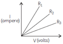
(a) R1 = R2 = R3
(b) R1 > R2 > R3
(c) R3 > R2 > R1
(d) R2 > R3 > R1
Answer
C
Question. When a 4 V battery is connected across an unknown resistor there is a current of 100 mA in the circuit. The value of the resistance of the resister is:
(a) 4 Ω
(b) 40 Ω
(c) 400 Ω
(d) 0.4 Ω
Answer
B
Question. The equivalent resistance of a series combination of two resistances is X Ohm. If the resistance are of 10 Ohm and 10 Ohm respectively, the value of X will be:
(a) 10 Ohm
(b) 20 Ohm
(c) 50 Ohm
(d) 40 Ohm
Answer
C
Question. The values of mA and μA are:
(a) 10–6 and 10–9 A respectively
(b) 10–3 and 10–6 A respectively
(c) 10–3 and 10–9 A respectively
(d) 10–6 and 10–3 A respectively
Answer
B
Question. A current of 1 A is drawn by a filament of an electric bulb. The number of electrons passing through a cross-section of the filament in 16 seconds would be roughly:
(a) 1020
(b) 1016
(c) 1018
(d) 1023
Answer
A
Question. Unit of electric power may also be expressed as:
(a) volt-ampere
(b) kilowatt-hour
(c) watt-second
(d) joule-second
Answer
A
Question. If the resistance of a certain copper wire is 1 Ω, then the resistance of a similar nichrome wire will be about:
(a) 25 Ω
(b) 30 Ω
(c) 60 Ω
(d) 45 Ω
Answer
C
Question. Electrical resistivity of a given metallic wire depends upon:
(a) Its length
(b) Its thickness
(c) Its shape
(d) Nature of the material
Answer
D
Question. At the time of short circuit, the electric current
in the circuit:
(a) vary continuously
(b) does not change
(c) reduces substantially
(d) increases heavily
Answer
D
Question. A current of 1 A is drawn by a filament of an electric bulb. Number of electron passing through a cross-section of the filament in 16 seconds would be roughly:
(a) 1020
(b) 1016
(c) 1018
(d) 1023
Answer
A
Question. A student plots V-I graphs for three samples of nichrome wire with resistances R1, R2 and R3. Choose from the following the statement that holds true for this graph.
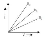
(a) R1 = R2 = R3
(b) R1 > R2 > R3
(c) R3 > R2 > R1
(d) R2 > R1 > R3
Answer
D
Assertion-Reason Questions
In each of the following questions, a statements of Assertion (A) is given followed by a corresponding statement of Reason (R). Select the correct answer to these questions from the codes (a), (b), (c) and (d) as given below:
(a) Both (A) and (R) are true and (R) is correct explanation of the (A).
(b) Both (A) and (R) are true but (R) is not correct explanation of the (A).
(c) (A) is true but (R) is false.
(d) (A) is false but (R) is true.
Question. Assertion (A) : At high temperatures, metal wires have a greater chance of short circuiting.
Reason (R) : Both resistance and resistivity of a material vary with temperature.
Answer : (b)
Question. Assertion (A) : When two ends of a metallic wire are connected across the terminals of a cell, then some potential difference is set up between its ends. The direction of electrons are from positive terminal to negative terminal of the cell.
Reason (R) : Electrons are flowing through the conductors from its higher potential to its lower potential end.
Answer : (a)
Question. Assertion : A fuse wire is always connected in parallel with the mainline.
Reason : If a current larger than the specified value flows through the circuit, fuse wire melts.
Answer : (D)
Question. Assertion (A) : Electric appliances with metallic body have three connections, whereas an electric bulb has a two pin connection.
Reason (R) : Three pin connections reduce heating of connecting wires.
Answer : (c)
Question. Assertion A : A 200 W bulbs glows with more brightness then 100 W bulbs.
Reason R : A 100 W bulb has more resistance than a 200 W bulb.
Answer : (a)
Question. Assertion (A) : In a purely resistive circuit, the source energy is dissipated in the form of heat.
Reason (R) : The potential difference across the ends of a conductor is directly proportional to the current flowing through it.
Answer : (b)
Question. Assertion (A) : In a series circuit, the current is constant throughout the electric circuit.
Reason (R) : All electric devices need equal currents to operate properly.
Answer : (c)
Passage Based Questions
Question. The following table given below shows the resistivity of three materials X, Y and Z.
Analyse the table and answer the following questions:
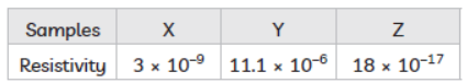
(A) Arrange the samples in increasing order of conductivity.
(B) Which of these is best conductor?
(C) Which are these is best insulator?
(a) X (b) Y
(c) Z (d) None of these
(D) Electrical resistivity of a given metallic wire depends upon:
(a) Its length
(b) Its thickness
(c) Its shape
(d) Nature of the material
Answer : (A) Conductivity is inversely propotional to resistivity so Y < X < Z.
(B) Z is the best insulator as it has least resistivity
Question. The following table given below shows the information about two heaters A and B.
Analyse the table and answers the following questions:
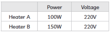
(A) Which Heater has higher resistance?
(B) If 1KWh is priced at 30 paise, which heater will be costlier if they run for 1 hours each?
(C) Unit of electric power may also be expressed as
(a) volt ampere (b) kilowatt hour
(c) watt second (d) joule second
Answer : (A)
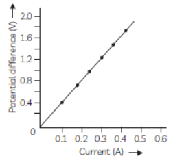
Question. The values of potential difference V applied across a resistor and the corresponding values of current I flowing in the resistor are plotted in a graph given below:
(A) Name the law which is illustrated by the above V-I graph.
(B) Write down the formula which states the relation between potential difference, current and resistance.
(C) What is the maximum resistance which can be made using five resistors each of 1/5 Ω?
(a) 1/5Ω
(b) 10 W
(c) 5 Ω
(d) 1 Ω
(D) Which of the following represents voltage?
Answer : (A) Ohm’s law
(B) Potential difference = Current x Resistance
(V = I x R)
(C) (d) 1 Ω
Imporatant Questions Electricity Class 10 Science
Very Short Anwer Type Questions
Question. Should the resistance of an ammeter be low or high? Give reason.
Answer : An ideal ammeter is one which has zero resistance. But that is not possible. Therefore,the resistance of an ammeter should be as close to zero as possible. If it is non-zero and
substantial, it will affect the current flowing through the circuit.
This is because an ammeter is connected in series in the circuit for the measurement of electric current.
Question. What will happen to the resistivity of a wire of length L if it is cut into three parts?
Answer : Resistivity of the wire will not change even when the wire is cut into three parts as resistivity is a characteristic of the material of the conductor and does not depend on the
physical dimensions of the conductor.
Question. The potential difference across the wire having fixed resistance is tripled. By how much does the electric power increase?
Answer : The electric power will increase by nine times when the potential difference across the wire having fixed resistance is tripled. According to Ohm’s law, potential difference V is proportional to current, I. Therefore, when V is made 3 times, I will increase 3 times. As Power P = VI, therefore, Power will increase by 9 times.
Question. Find the minimum rating of fuse that can be safely used on a line on which two 1.1 KW electric geysers are to run simultaneously.
The supply voltage is 220 V.
Answer : Power P = VI. As the two geysers have power rating 1.1 kW or 1100 W and are connected in parallel, each geyser draws a current I = P/V =
1100/220 A = 5 A.
Therefore, total current drawn = 10 A, which should be the minimum rating of fuse that can be safely used.
Short Anwer Type Questions
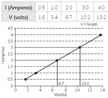
Question. The values of current I flowing in a given resistor for the corresponding values of potential difference V across the resistor are given below:
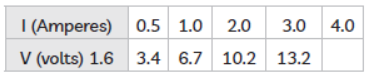
Plot a graph between V and I and also calculate the resistance of that resistor.
Answer : (A) The voltage is plotted on x-axis and current is plotted on y-axis. The values of the current for different values of the voltage are shown in the given table.
Question. What is the commercial unit of electrical energy? Represent it in terms of joules.
Answer : The commercial unit of electric energy is kilowatt hour (kW h), commonly known as ‘unit’.
1 kW h = 1000 watt × 3600 second
= 3.6 × 10⁶ watt second
= 3.6 × 10⁶ joule (J)
Question. A V-I graph for a nichrome wire is given below. What do you infer from this graph?
Draw a labelled circuit diagram to obtain such a graph.
Answer : We infer from the graph that V/I is a constant ratio. i.e., V a I which is ohm’s law. This constant ratio is called the resistance (R) of the conductor.
In 1827, a German physicist G. Siman Ohm found out the relationship between the current (I). Fowing in a metallic wire and the potential difference across its terminals.
The potential difference (v) across the ends of a given metallic wire is in an electric circuit is directly proportional to the current flowing through it, provided its temperature remains
the same.
Va
V/I = Constant
V = IR
Question. (A) Draw a diagram to show how two resistors R1 and R2 should be connected so that the total resistance of the circuit is minimum.
(B) In a circuit, if two resistors of 4 Ω and 8 Ω are connected in parallel, find ratio of current passing through the two resistors.
Answer : (A) Two resistors R1 and R2 should be connected in parallel so that the effective resistance of the circuit is minimum.
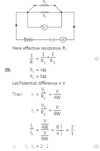
Question. (A) State Ohm’s law.
(B) A piece of wire of resistance 20 Ohms is drawn out so that its length is increased to twice of its original length. Calculate the resistance of the wire in the new situation.
Answer : (A) Ohm’s law states that under no same temperature, electric current flowing through an ideal conductor is directly proportional to the potential difference across its ends.
V ∝ I
or V/I = constant = R
or V = IR
R is a constant for the given metallic wire at a given temperature and is called its resistance.
(B) Given R = 20 Ω
Let length of wire is L and when it is drawn out its new length will become 2L.
The volume of wire in both the situations remains constant. So, if the length of wire is doubled, the area of cross section of wire becomes half.
So, the new resistance of the wire, (Image 319)
Question. Answer the following questions:
(A) List a distinguishing feature between the resistance and resistivity of a conductor.
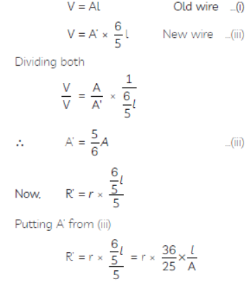
(B) A wire is stretched so that its length becomes 6/5 times its original length. If its original resistance is 25 ohm, find its new resistance and resistivity.
Answer : (A) A distinguishing feature between the resistance and resistivity of a conductor:
Resistance of a conductor depends on the length and area of cross- section of the conductor. On the other hand, resistivity depends upon the properties of the metal used in conductor. Unit of resistance is ohm and unit of resistivity is ohm-meter.
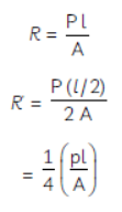
(B) We know that
R = ρ 1/A = 25
(1) Resistivity of wire is independent of its length or/and area of cross-section.
Therefore, increasing the length of wire by 6/5
times results in no change in resistivity.
(2) Where length of wire increases or decreases, the volume of wire remains the same but the area of wire changes as well
Question. Why is parallel arrangement used in domestic wiring?
Answer : Parallel arrangement is used in domestic wiring due to the following reasons:
• Each device will have the same voltage which is equal to the voltage of the supply.
• If two or more devices are used at the same time, then each appliance will be able to draw the required current.
• If one of the devices fails, then the other keeps working.
Question. An electric iron is used on a 240 V supply and draws a current of 4 Ampere.
(A) What is its power?
(B) What is its resistance?
(C) What is the cost of using the iron for the month of January 10 hours a day if 1 KWH costs rupees 3.40?
Answer : An electric iron is used on a 240 V supply and draws a current of 4 Ampere. Therefore,
Voltage,
V = 240V
Current, I = 4A
No. of days in January = 31
\ Time, t = 31 x 10 hours = 310 hours.
(A) Power, P = V x I
= 240 × 4 = 960 W1
(B) Resistance,
R = V?I = 240/4 = 60 ohms 1
(C) Electric energy consumed = Power x Time =
960 × 310 = 297600 watt hours
[1 KW = 1000 W] = 297.6 KWH
Cost of using the heater for 310 hours =
297.6 × ` 3.40 = ` 1011.84
Question. Which one of the following is the correct setup for studying the dependence of the current on the potential difference across a resistor and why?
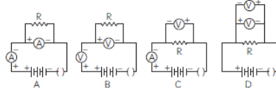
Answer : Set up A is correct.
The voltmeter should be connected in parallel to the resistor across which potential difference is to be measured and ammeter should be connected in series.
The Positive terminals of voltmeter and ammeter should be connected to the positive terminal of source voltage.
Question. Study the circuit shown in which three identical bulbs B1, B2 and B3 are connected in parallel with a battery of 4.5V.
(A) What will happen to the glow of other two bulbs if the bulb B3 gets fused?
(B) If the wattage of each bulb is 1.5 W, how much reading will the ammeter A show when all the three bulbs glow simultaneously?
(C) Find the total resistance of the circuit.
Answer : (A) As the bulbs are in parallel connection, even if bulb B3 gets fused the remaining twobu lbs will glow with the same brightness.
(B) Same current flows through all the bulbs as they are connected in parallel.
Total wattage will be added
V = 4.5 V
P = 1.5 W + 1.5 W + 1.5
W = 4.5 W
P = VI
So i = P?V = 4.5W /4.5 V = 1A
The ammeter reading would be 1 Ampere
(C) Also we know that
V = IR
Therefore R = V/I = 4.5V /1A = 4.5 ohms
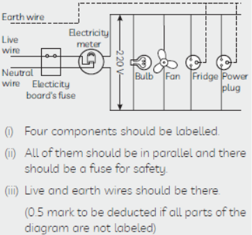
Question. Suppose your parents have constructed a two room house and you want that in the living 3 room there should be a provision of one electric bulb, one electric fan, a refrigerator and a plug point for appliances of power up to 2 kilowatt. Draw a circuit diagram showing electric fuse and earthing as safety devices.
Answer :
Long Anwer Type Questions
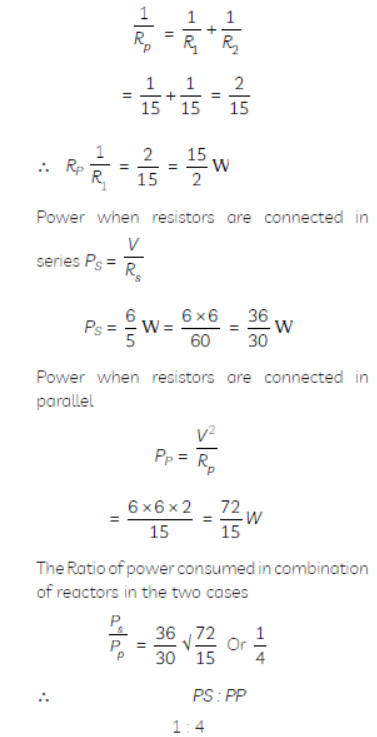
Question. Two identical resistors, each of resistance 15 W, are connected in (i) series, and (ii) parallel, in turn to a battery of 6 V. Calculate the ratio of the power consumed in the combination of resistors in each case.
Answer : R = 15 W
V = 6V
Since the resistors are identical and two resistors
are given so R1 = R2
(i) In series
Question. How will you conclude that the same potential difference (voltage) exists across three resistors connected in a parallel arrangement to a battery?
Answer : The same potential difference exists across three resistors connected in a parallel arrangement to a battery can be concluded as follows:
• Take three resistors R1, R2 and R3 and connect these resistances in parallel with a voltmeter, an ammeter, a key and a battery of known voltage as shown in the figure given.
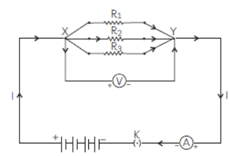
• Plug the key and measure the potential difference when all the three resistors are connected in parallel.
• Open the key and remove the ammeter and voltmeter from the circuit and insert the voltmeter in parallel with R1 and the ammeter in series with the resistor R1, as
shown in the figure given below. Again, the voltmeter and ammeter readings are recorded.
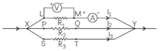
• Similarly, measure the potential differences across resistances R2 and R3.
Observations:
It is observed that the voltmeter shows the same reading in all these conditions. This shows that the voltage or potential difference across each resistor is the same and equal to the potential difference across the combination
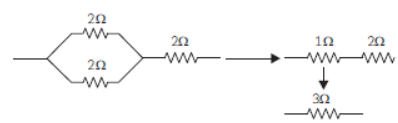
Question. (A) A 6 W resistance wire is doubled on itself.
Calculate the new resistance of the wire.
(B) Three 2 W resistors A, B and C are connected in such a way that the total resistance of the combination is 3 W. Show the arrangement of the three resistors and justify your answer.
Answer : (A) R = 6 W
When the wire of length l and crosssectional area A is doubled on itself, its length becomes ½ and cross-section area becomes 2A.
New resistance of the wire will be 1.5 W (B) To get a total resistance of 3 W from three resistors A, B and C, two resistors of resistances 2 W each should be connected in parallel. Their equivalent resistance is:
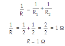
This combination of equivalent resistance 1 W should be connected in series with the resistor of resistance 2 W. So that the equivalent resistance becomes 1Ω + 2Ω = 3Ω